Archive for ‘c#’

settembre 5, 2011

Rearrange the mesh after WeaverBird’s subdivisions (part 2)

In this second part I explain a possible solution to the problem of rearranging the order of faces and vertices. The default order from subdivision components of WeaverBird is presented in a non-intuitive form. The default order of the mesh after three levels of subdivision of one quad-face looks like this:

scheme_mesh_subdivisions_3

default distribution of faces after three levels of subdivision

This distribution comes from the progressive rotation and repetition of the basic counterclockwise order:

 ----------
|          |
|  3    2  |
|          |
|  0    1  |
|          |
 ----------


So what I’m looking for is a rearrangement of the order of faces and vertices that is similar to a grid arranged in rows and columns. To obtain this I have decomposed the problem into two steps.
In the first step I hypothesized a more simple distribution:

scheme_mesh_subdivisions_1

more simple distribution

Now we consider the coordinates of every face in function of their parents faces. For exemple:


0 ==> {0;0;0}
1 ==> {0;0;1}
2 ==> {0;0;2}
3 ==> {0;0;3}
4 ==> {0;1;0}
5 ==> {0;1;1}
...
26 => {1;2;2}
...
64 => {3;3;3}


Looking for a rule rows for columns we can describe the progression of individual rows via binary numbers. For exemple the first row looks like:


{0;0;0}, {0;0;1}, {0;1;0}, {0;1;1}, {1;0;0}, {1;0;1}, {1;1;0}, {1;1;1}


This sequence represents the paths of the faces belonging to the first row from the bottom. If we consider the same sequence for every row and a similar one for columns then we will be able to describe every number in function of its row and columns index. For exemple we can write 26 like:


26 => (4, 3) => ({1;0;0}, {0;1;1})


and we can easily get the global path:


26 => {1;0;0} + 2*{0;1;1} = {1;2;2}


now we are ready for second step.

In second step we will switch from linear to counterclockwise distribution. To do that simply flip the 2 with 3, getting a new distribution:

scheme_mesh_subdivisions_2

counterclockwise distribution

Then we see the correspondence between the new order and flipped paths. Looking at our friend 26:

26 => {1;2;2} ==flip==> {1;3;3}


Now there is a last step. We have to consider the progressive rotations of subdivided faces. Every new subdivision level new faces rotate around the center of the parent face of one position counterclockwise (+) for every level and a number of positions corresponding to superior path index clockwise (-). For exemple:


n: {A0; B0; C0}
A1 = (A0 + 0)%4
B1 = (B0 + 1 - A1)%4
C1 = (C0 + 2 - B1)%4

26 => {1;3;3} ==rotating==> {1;3;2}


At this point we can take the numbers from paths {A;B;C} and give them a new index:


ID = A*4^2 + B*4^1 + C*4^0


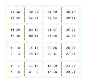
At the end of the process the output looks like that:

rearrange_faces

rearranging of four faces after three subdivision levels


If you want you can try my C# script. To work, it must be placed in succession to my previous script for rearranging single face’s vertices order. Look at my Ghrasshopper definition for better understand how it works:
download Rearrange Faces.gh

settembre 4, 2011

Rearrange the mesh after WeaverBird’s subdivisions (part 1)

This script was developed to be used in succession to the components of simple subdivision and Catmull-Clark subdivision introduced in Grasshopper thanks to the plugin WeaverBird developed by Giulio Piacentino.

One of the difficulties of working with subdivided meshes is the not easy acces to different faces. The difficulty stems from two fundamental aspects: the order of the vertices of the individual faces is not always the same, but it was caracterized by a different shift in each subdivision for each face. The second aspect concerns the order of indexing of individual faces and vertices. In fact, these orders do not coincide with the rows and columns of the corresponding grid.

To solve the first problem you need to go and investigate the slip rule, which follows a rule for incremental four faces derived from the mesh of departure according to their order and the number of subdivisions.

Look at the image to better understand the difference in output, if we decide for example of triangular faces using vertices [0, 1, 2] of each quad-face:

tidyng vertices of single faces

tessellation by triangles (0, 1, 2): before and after rearranging of relative order of the vertices

It is possible to download the Grasshopper definition for vertices shifting. It includes my script in C # together with an explanation and a different version of the process with standard GH components both edited by Mirco Bianchini

download Shift Vertex Order.gh

Because the orientation of vertices depends on the order of faces of starting low-poly mesh, I insert in my c# component vertex the possibility to correct manually through a list of integers containing the individual shifting values for faces of starting mesh. By default I give a shifting value of 1 for the first face. Disconnecting the panel it turns off automatically.

aprile 6, 2011

voxel analysis for implicit surfaces

This is my first test with implicit surfaces. I tried to voxelize a sort of rheotomic surface, defined by rules of iso-distance between nearest elements of two differtent groups (1 point+2 curves for first group and 2 points+1 curve for the second one).

In a first moment, I tested the brute-force samplyng method, in order to search for a way to sample points belonging to implicit surfaces. This expensive method consists of analyzing all possible solutions and the subsequent evaluation of results. In this case I needed to verify each point of my 3D grid and improving the resolution, i obtained  8^n points every n divisions of main domain.

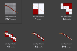
A better solution consists in a progressive analysis: starting from a domain, and progressively dividing positive matched cubes (later I learned that this approach already exists with the name of Quadtree):

Sampling Scheme

Explanation of progressive sampling method.

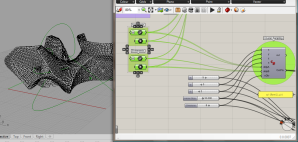
Coding it with c# in grasshopper, I obtained a relatively complex point cloud:

Rheotomic surface_002

Point Cloud otup in grasshopper

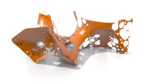
This coarse approximation isn’t at the moment enough accurated for obtaining clean surfaces, however I tried to connect resulting point-cloud with MeshLab. After a quick editing in Blender, I rendered the output:

Rheotomic surface_001

Final Mesh

At the moment I’m working on the improvement of the quality of point-cloud and subsequent elegance of the resulting mesh.